ONE-YEAR MATERIALS + FOOTWEAR STUDY
From material
to movement.
A pressure-guided lattice insole developed through custom elastomer research, parametric modeling, and a custom force–deformation testing device.

01 / THE QUESTION
Can an insole respond differently to different parts of the foot?
A uniform foam block treats every region the same. I wanted to test whether a spatially tuned lattice could balance cushioning and support where the foot actually needs it.
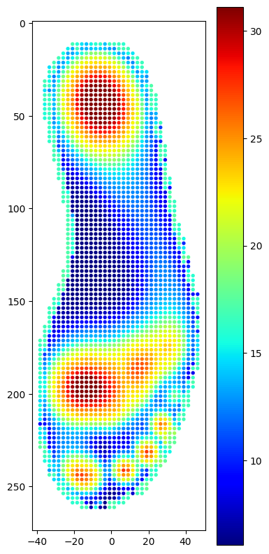
Observe
Red and orange regions concentrate around the heel and forefoot; the arch carries comparatively less load.
Translate
Convert the pressure field into regional design variables: lattice family, cell size, relative density, and material hardness.
Test
Compare structures mechanically before selecting a full insole configuration.
02 / THE MATERIAL
Before designing the lattice, I built the material.
A high-resilience elastomer, similar in feel to TPU, became the basis for every geometry experiment. The comparison uses two hardness levels: Shore A 85 and Shore A 95. Test records and material provenance will be added alongside the results.
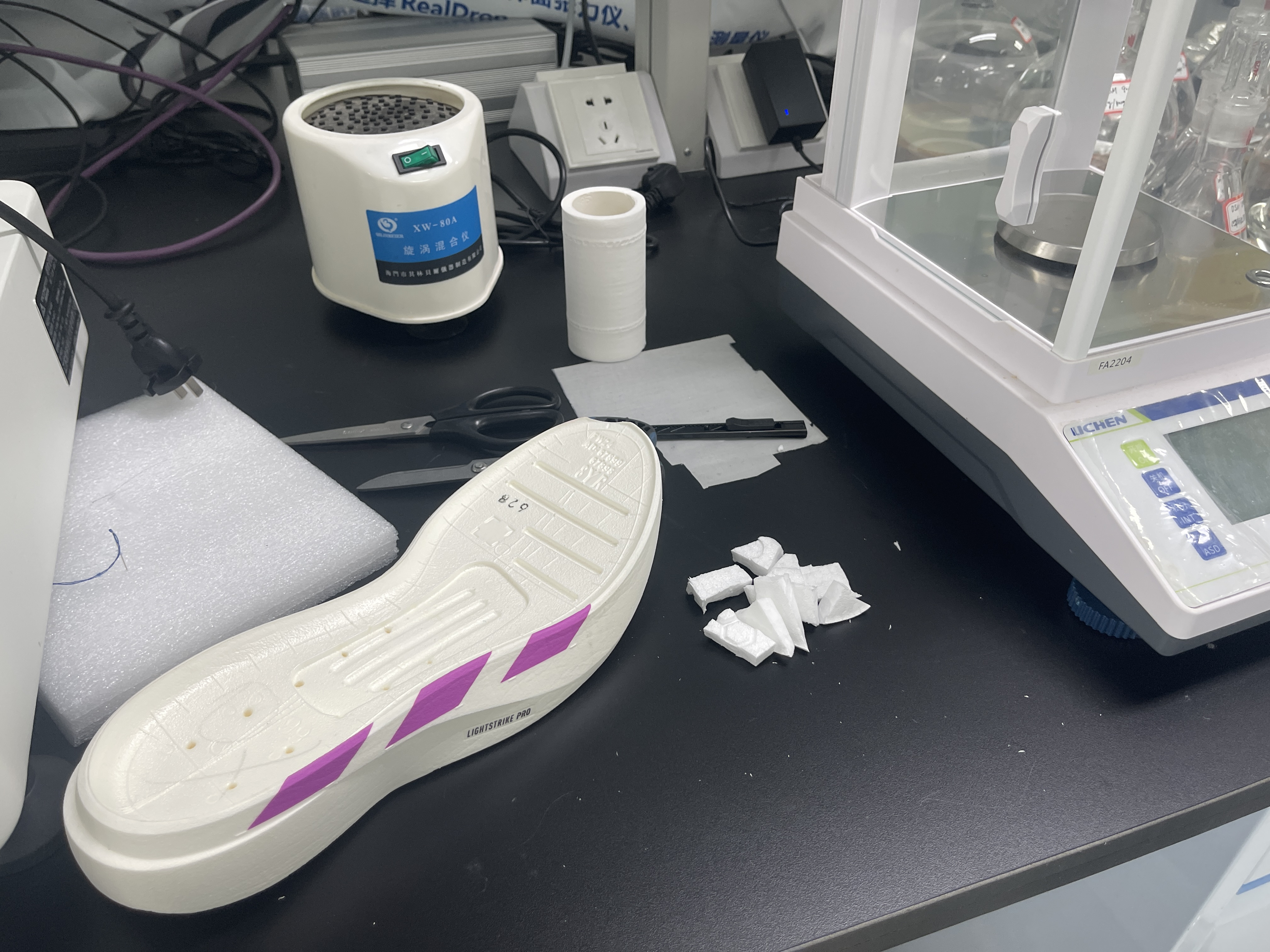 01 / Sample preparation
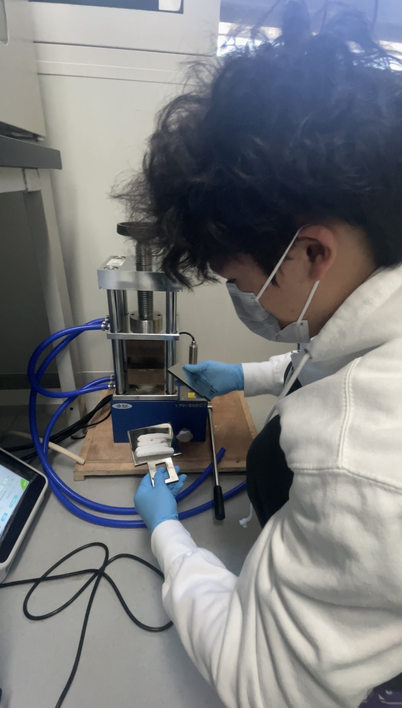 02 / Compression test
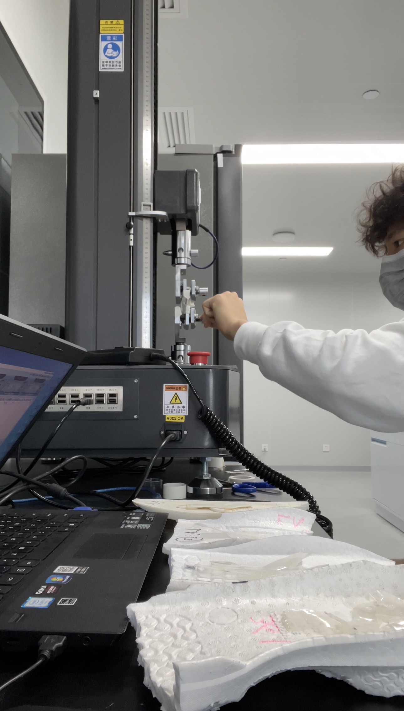 03 / Tensile test
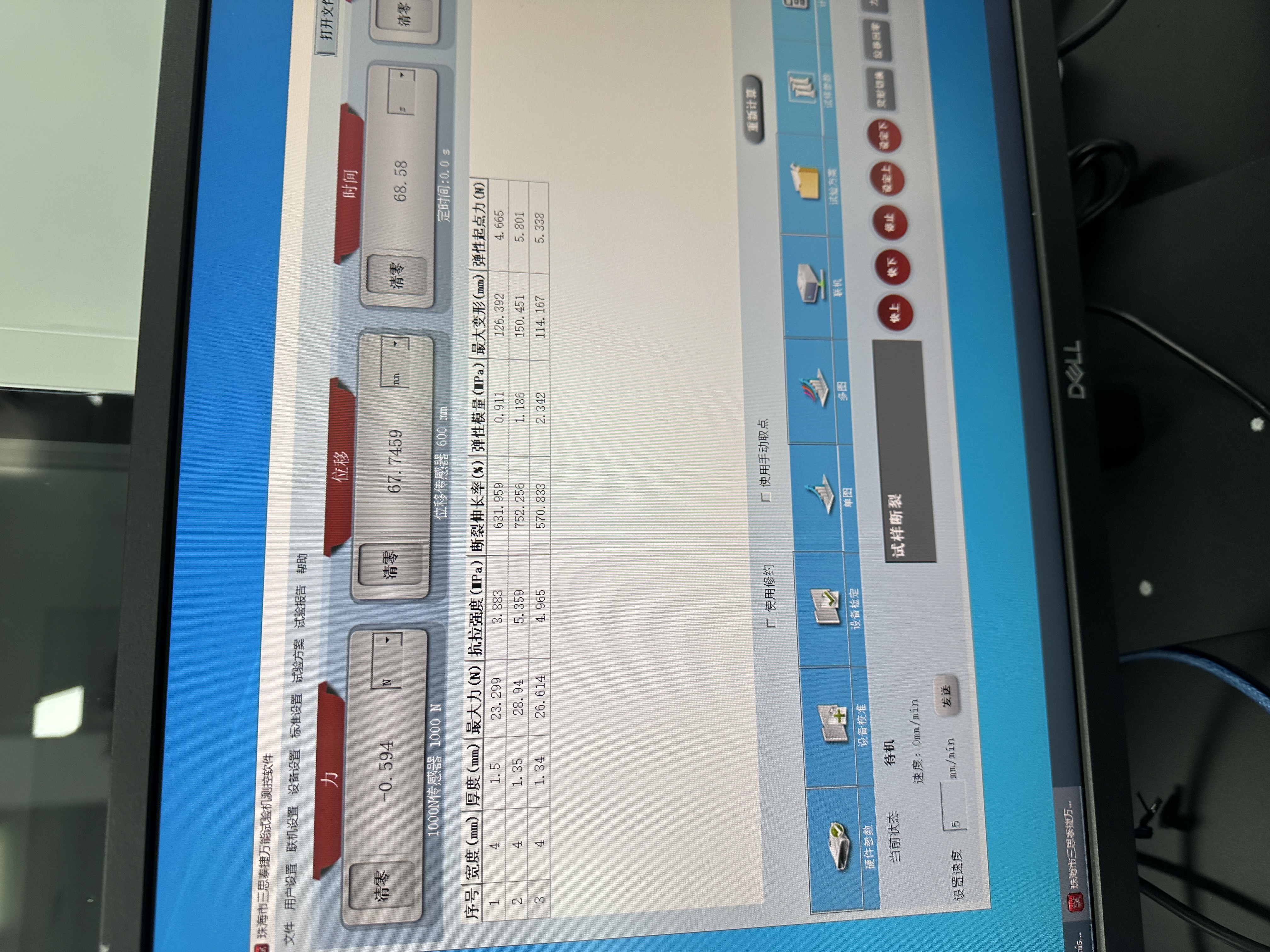 04 / Test records
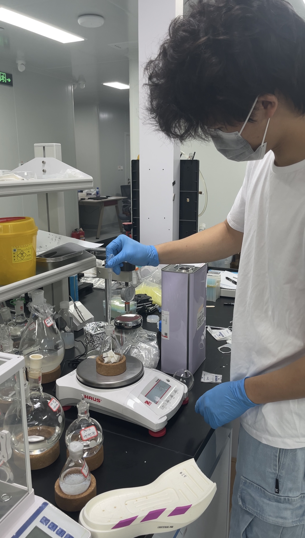 05 / Material preparation
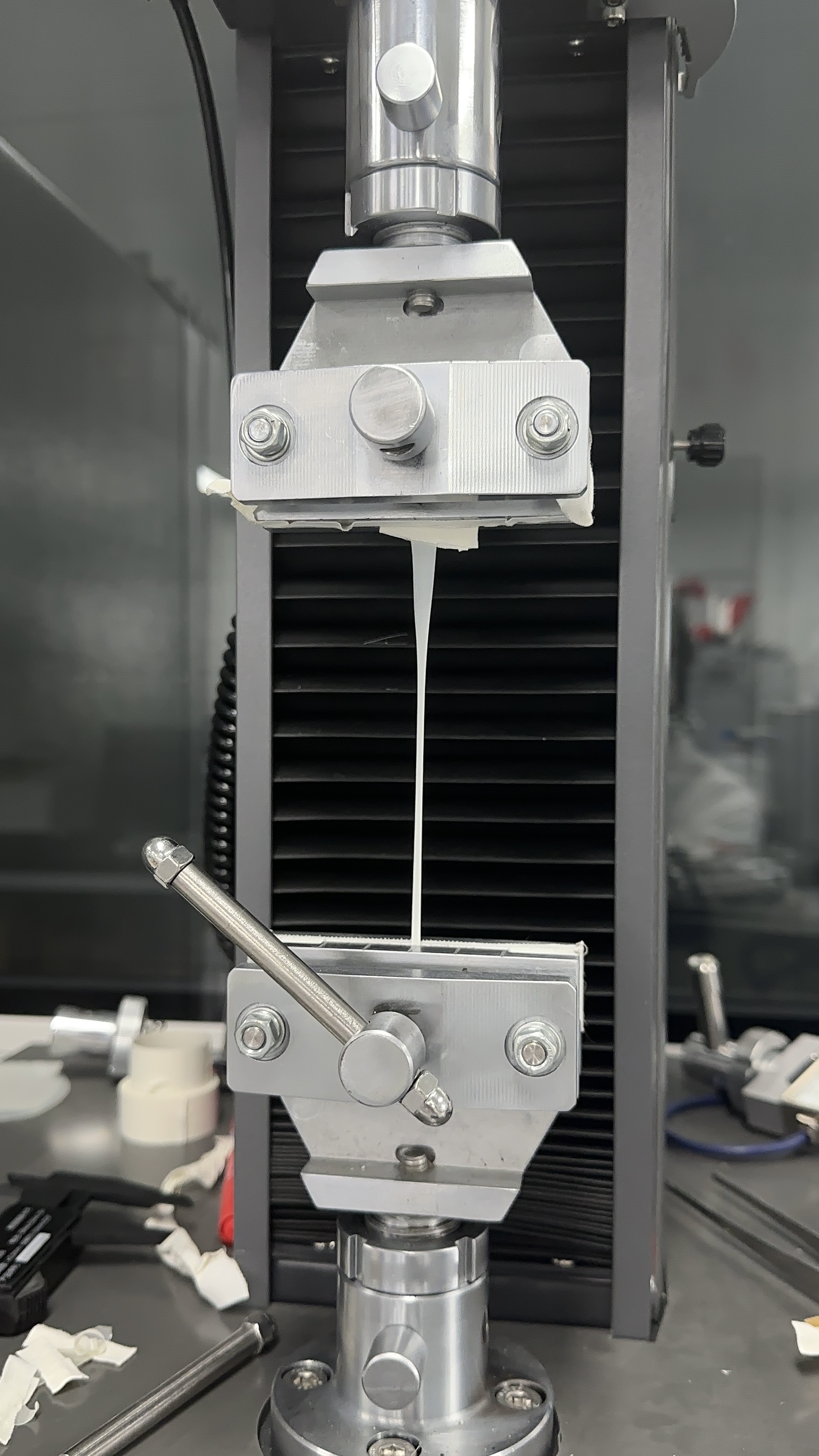 06 / Tensile testing
Lower hardness candidate for compliant, energy-absorbing regions.
Higher hardness candidate for stability and load-bearing regions.
After testing both Shore A 85 and Shore A 95, I found that 85A was too soft for structural lattice tests. The following prototypes therefore use 95A as the main material.
Hardness is one material variable. Compression behavior and recovery need separate measurements; fatigue testing is a proposed next step.
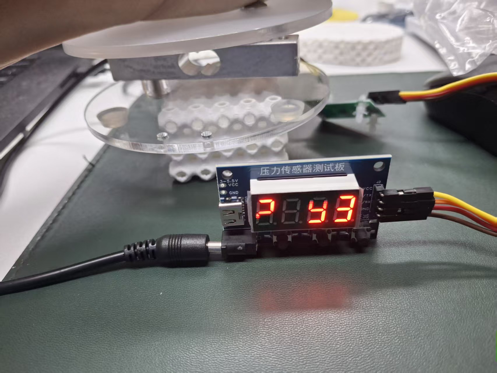
02.1 / DIY INSTRUMENT
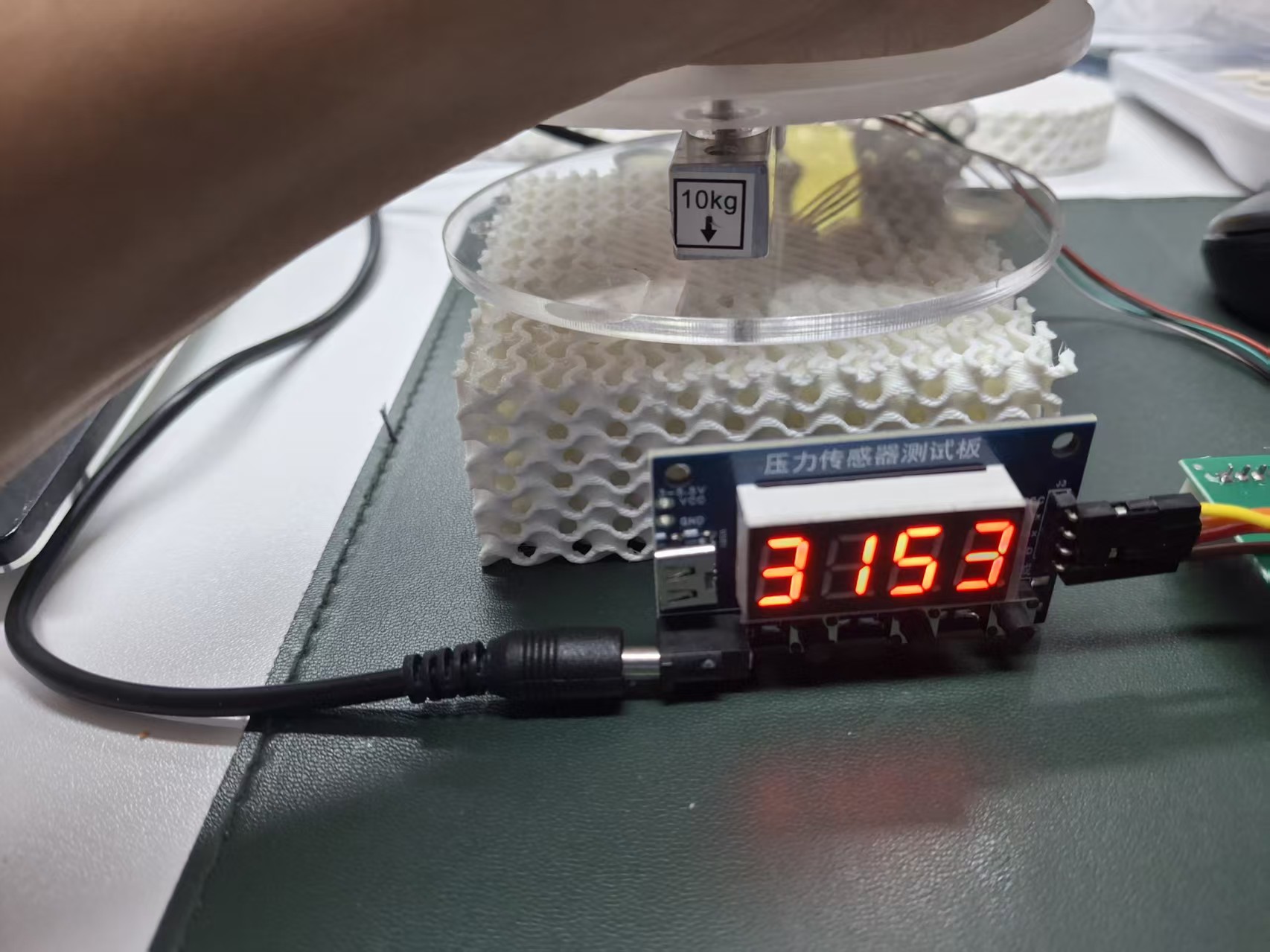
A small rig made the material measurable.
We tried using a force scale to record the load and observe how the structures deformed. We collected some data, but I felt that the numbers alone did not convey how the different structures would feel underfoot. I wanted to use my own body weight and feel their elasticity through direct contact with my feet. To me, this would make the differences more tangible.
03 / THE DESIGN SPACE
Twelve structures to compare.
I am comparing twelve lattice structures using 85A and 95A materials. These photographs document the physical samples. Select a photograph to view the original in detail.
04 / THE SYSTEM
Pressure becomes a rule for geometry.
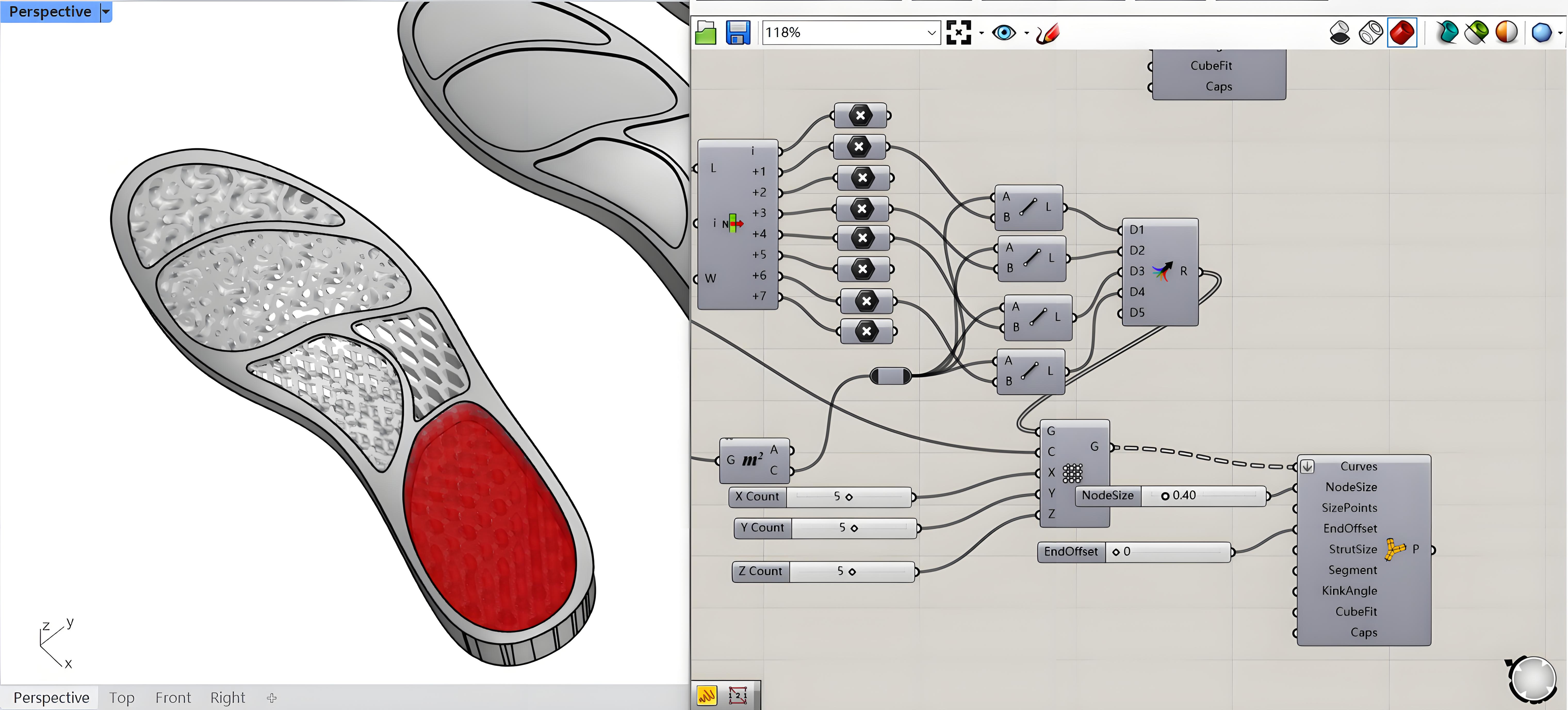
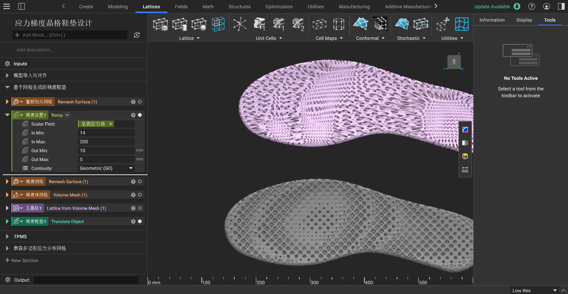
I used Rhino + Grasshopper for form development and parametric control.
pressure
regions
lattice
measure
OBSERVATION / FIRST WEAR
Different regions, different responses.
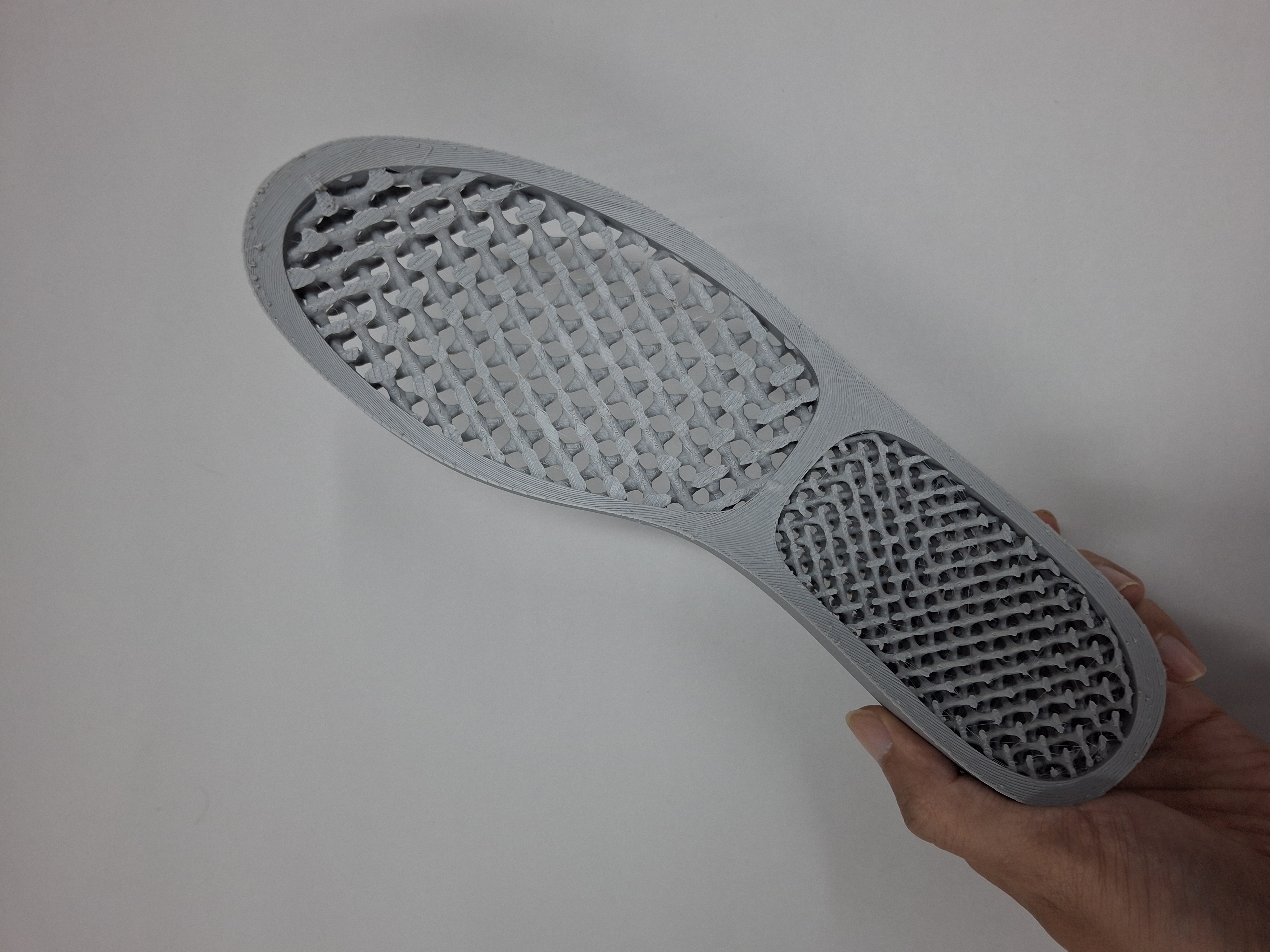
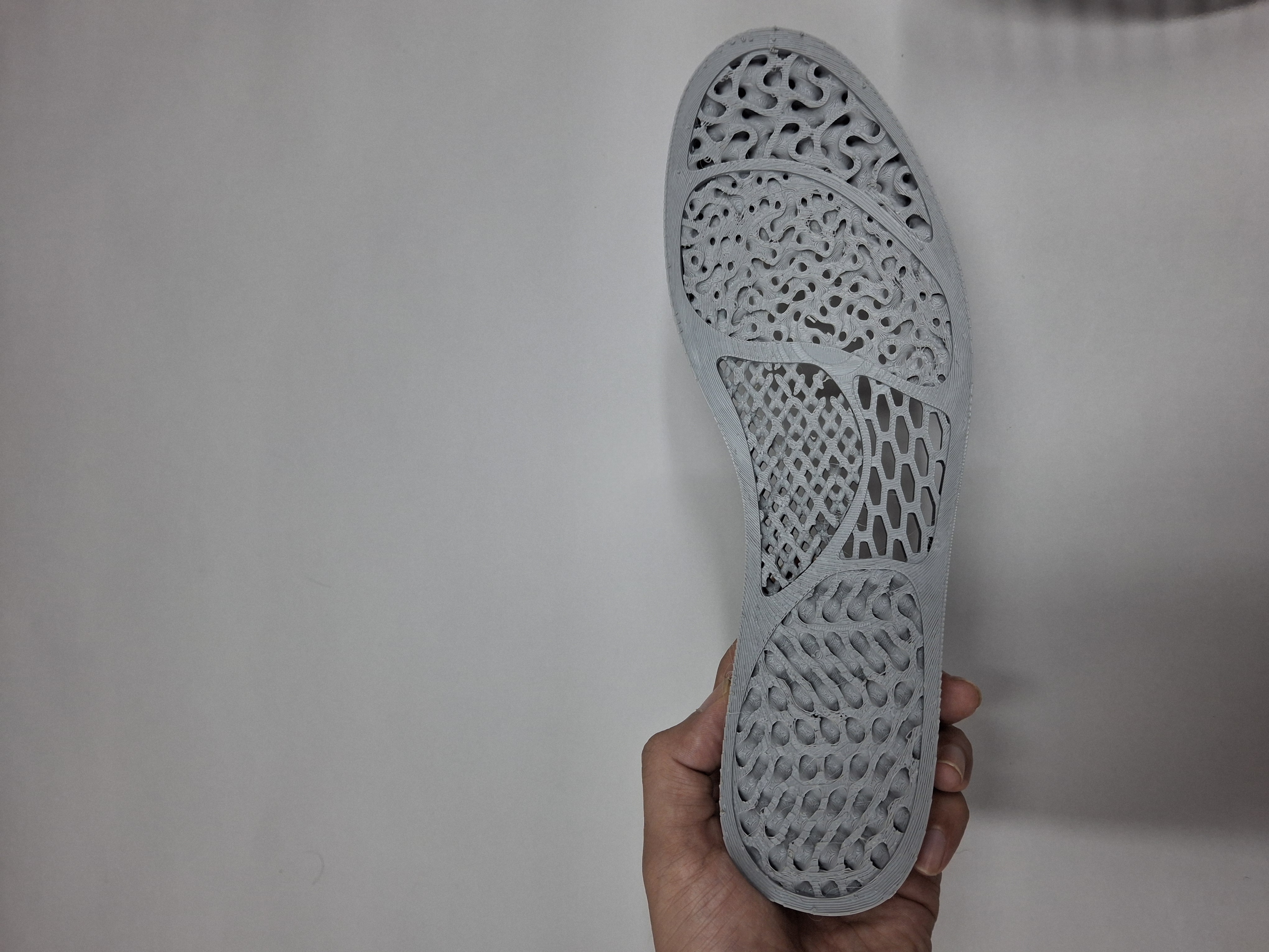
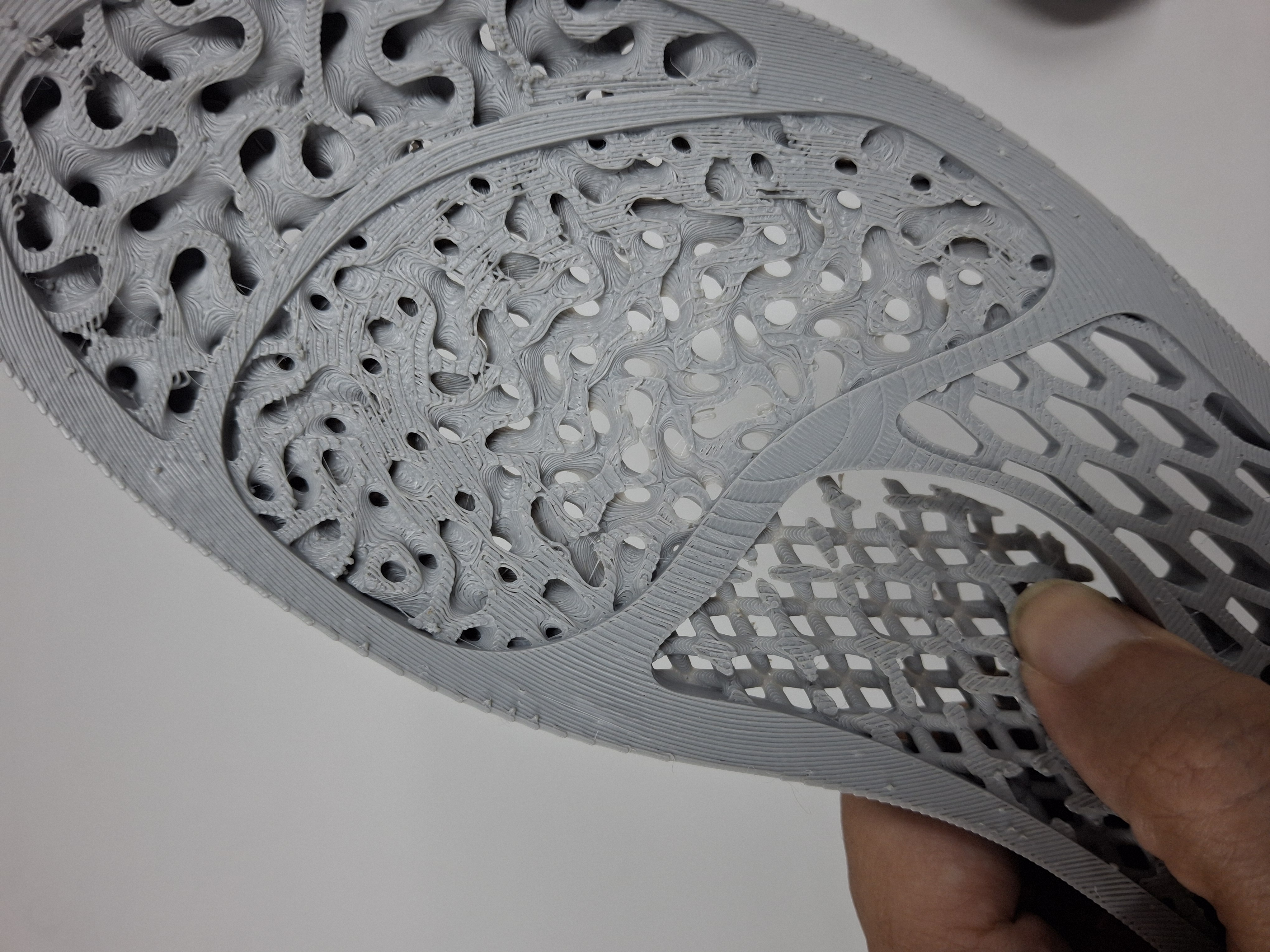
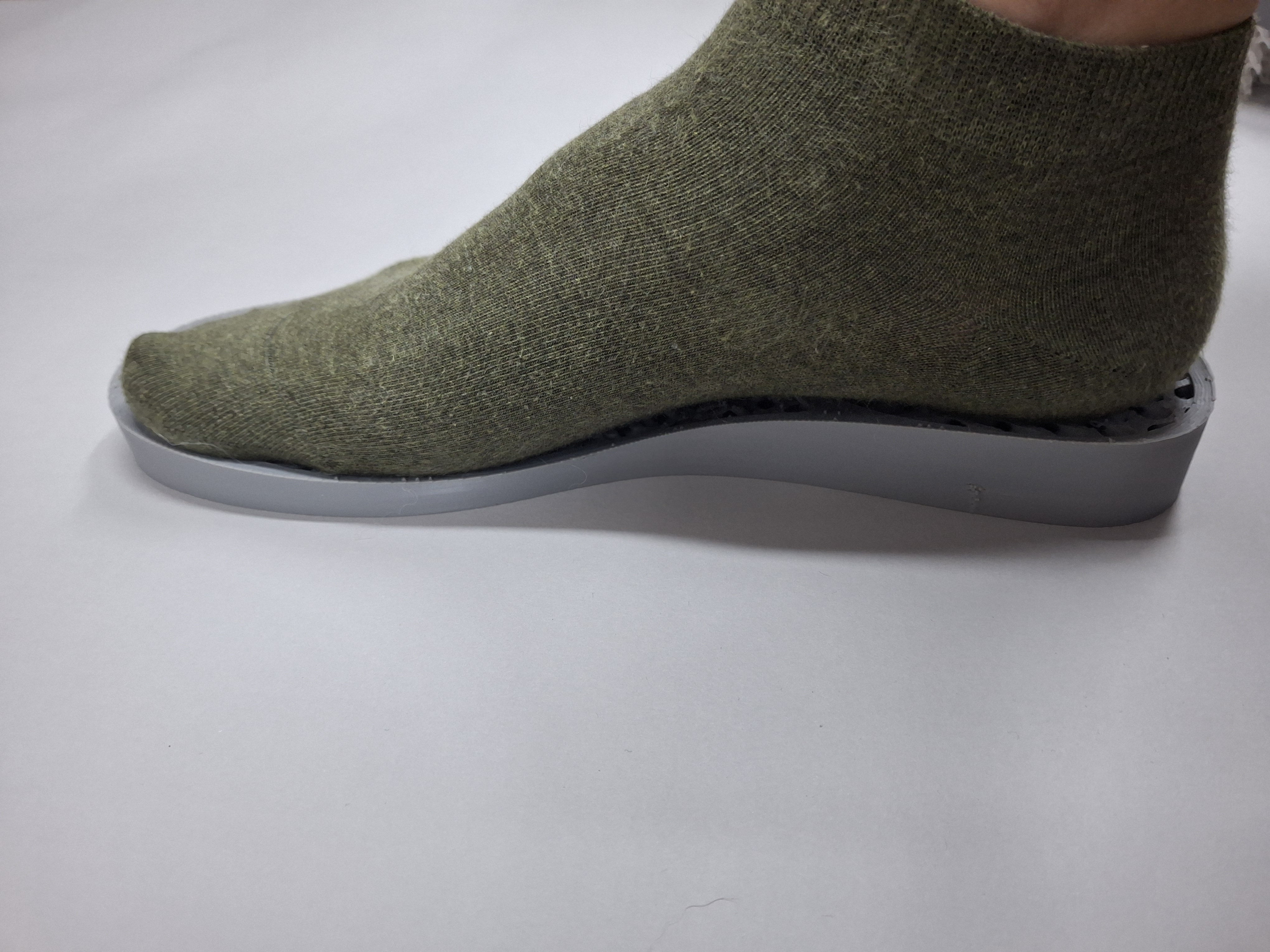
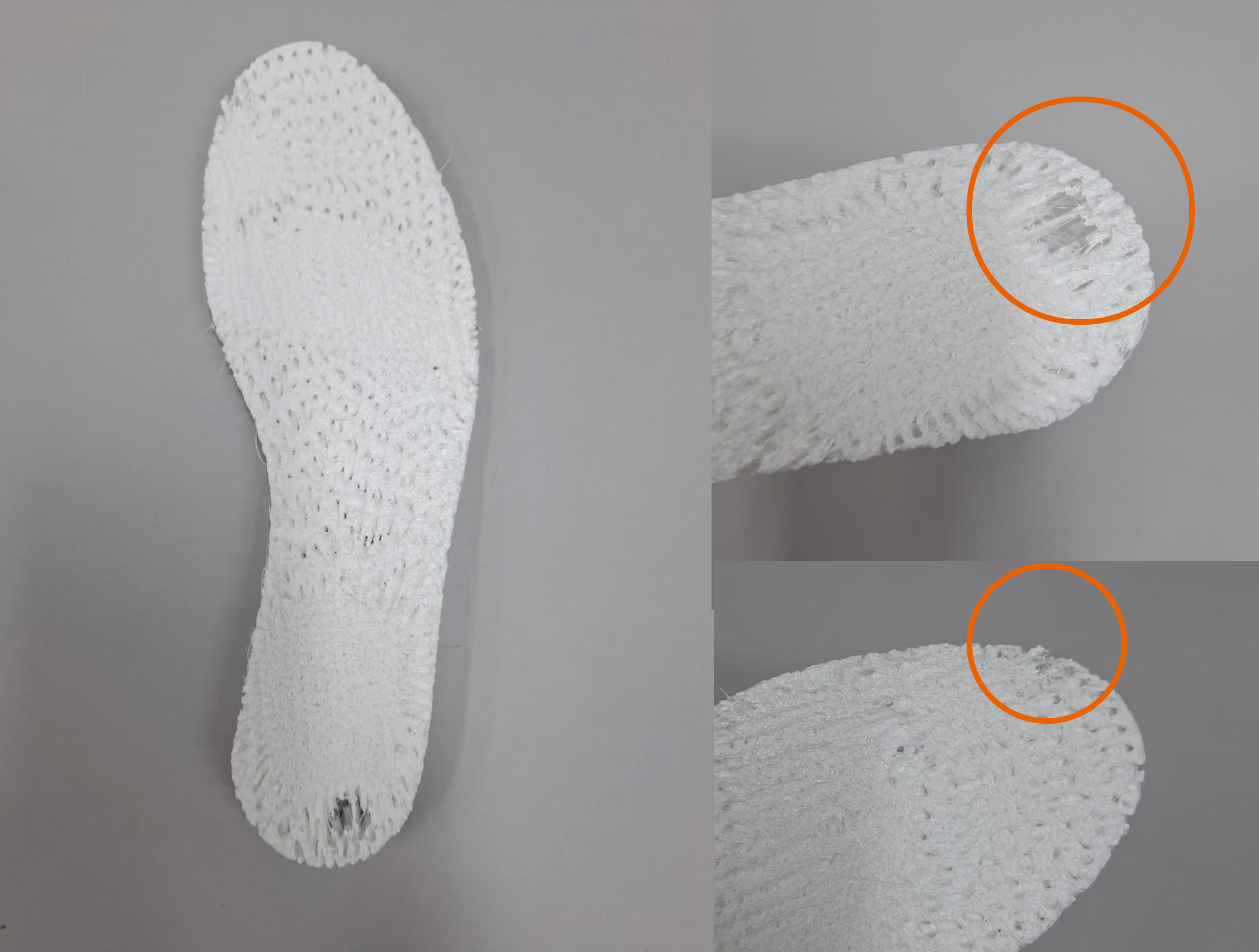
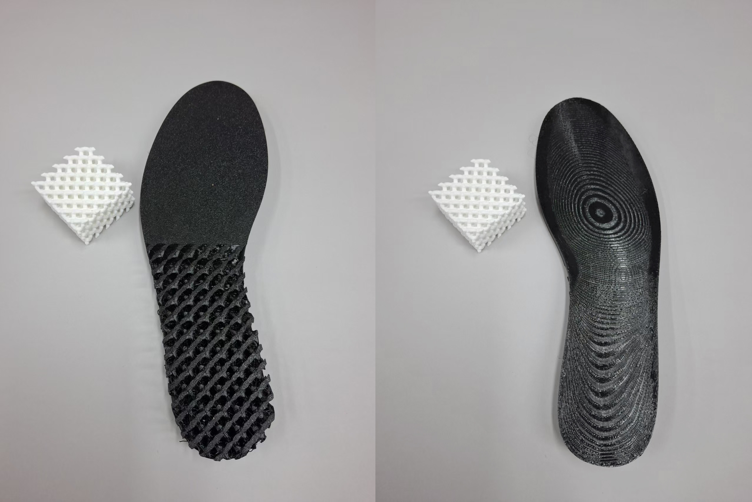
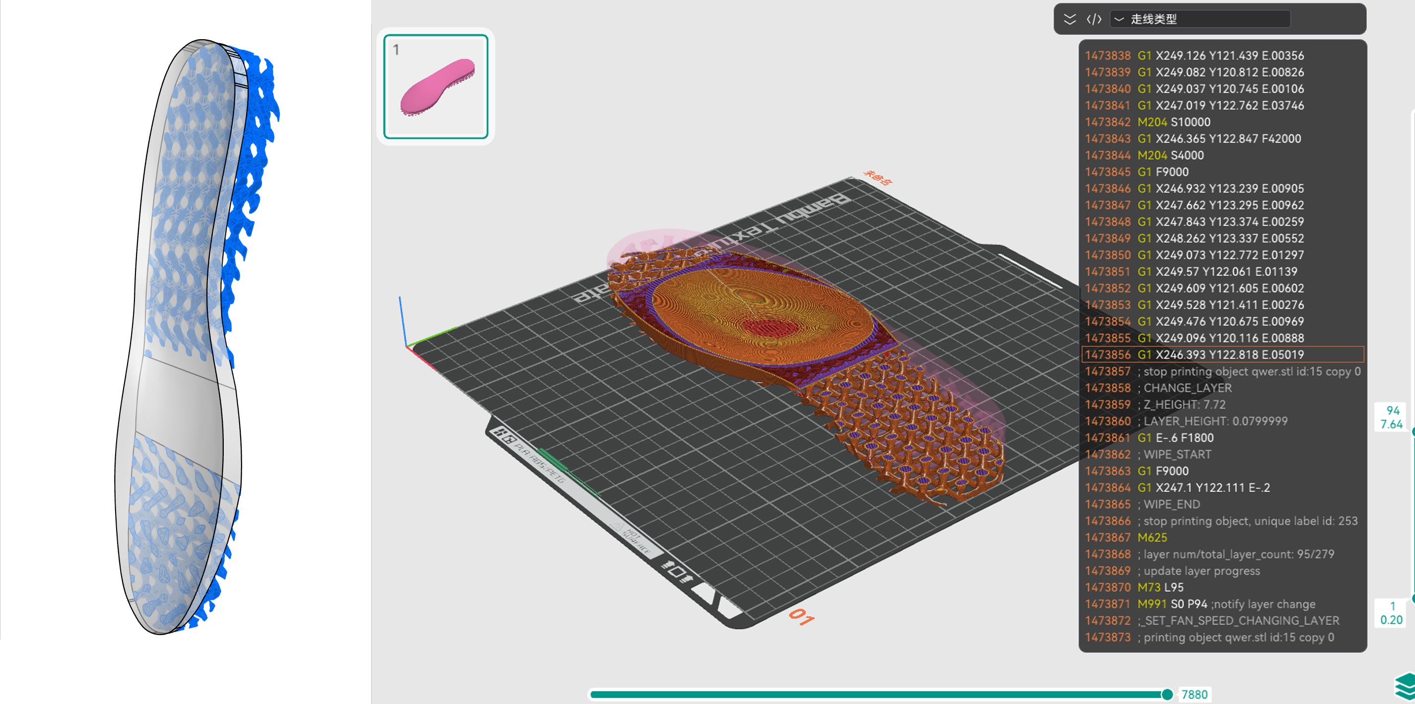
This prototype combines several lattice structures across the insole, so each region has a different elastic response. Underfoot, the changing textures feel almost like a massage. The first wear test also revealed problems to solve: the hard perimeter edges feel sharp and may wear or detach over time, while the heel region can sink and leave an uncomfortable edge.
05 / THE REFLECTION
Design became a loop, not a single answer.
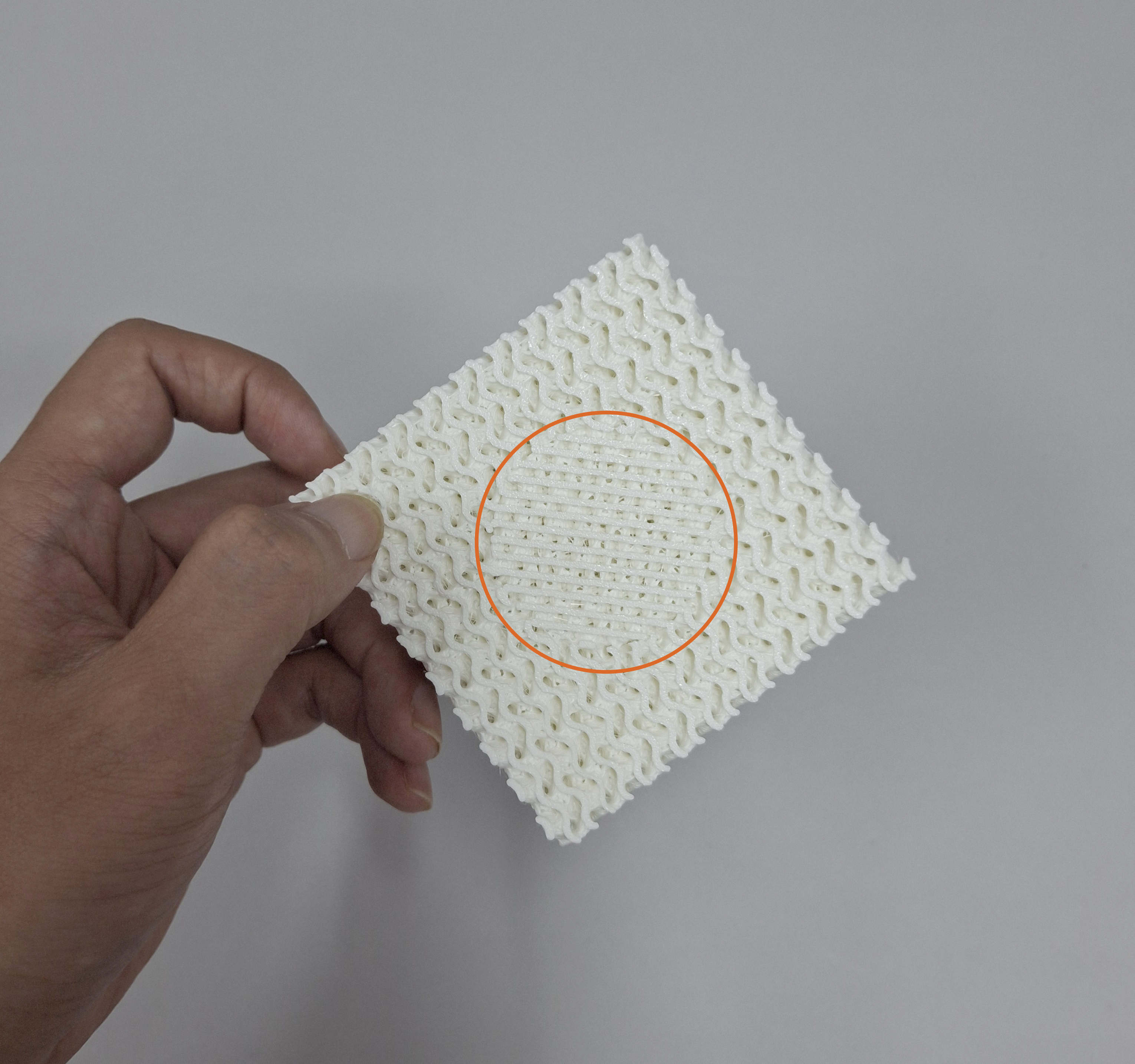
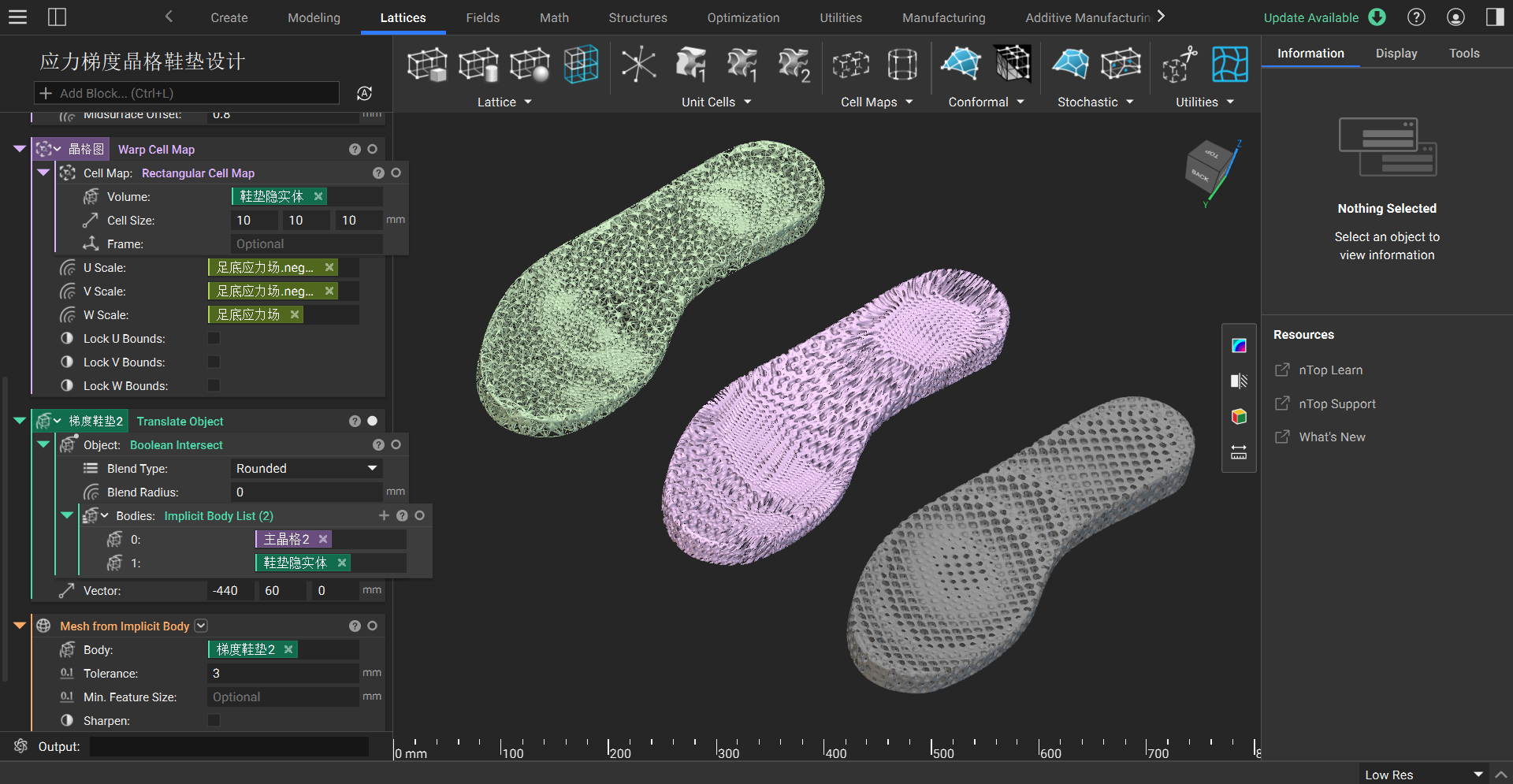
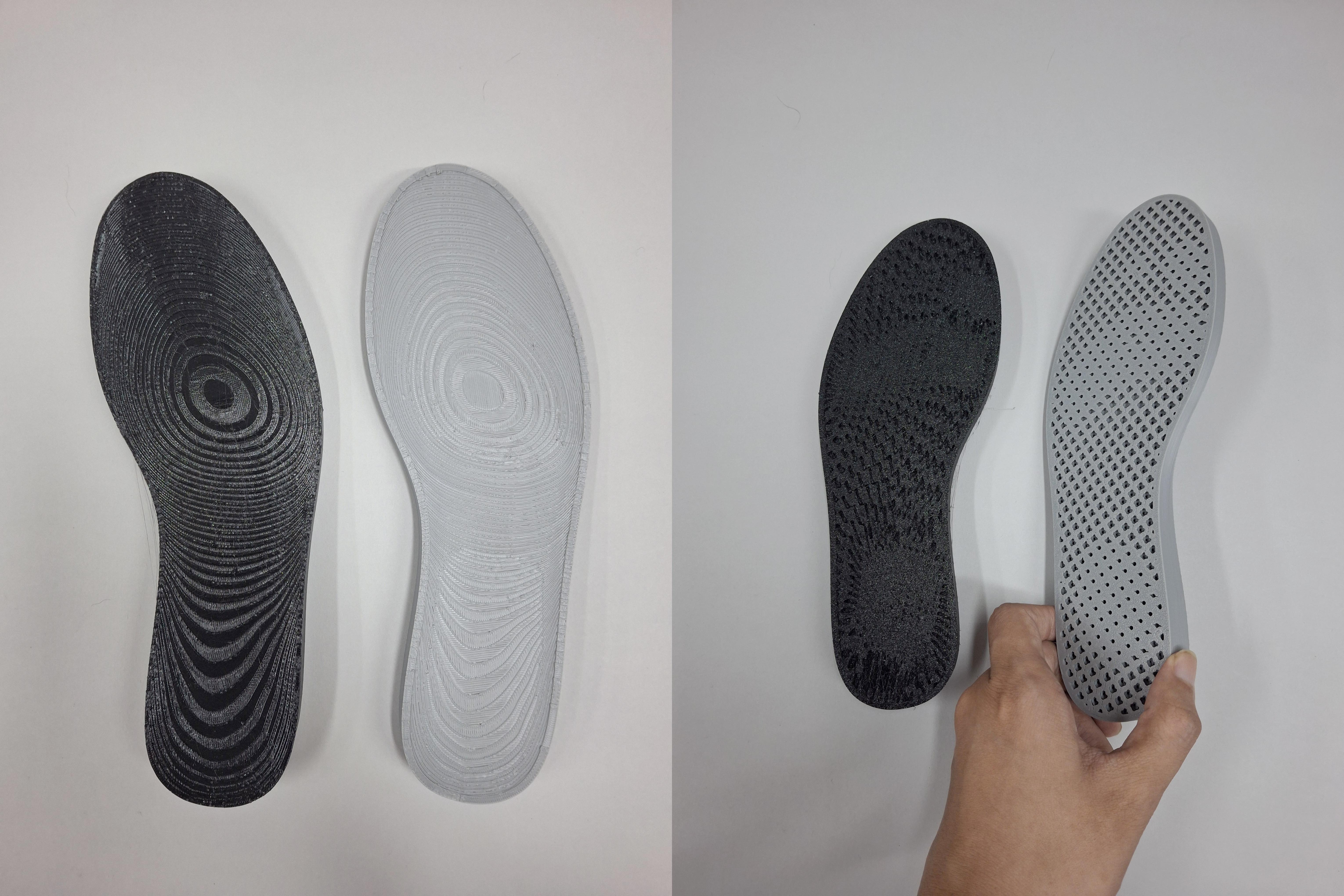
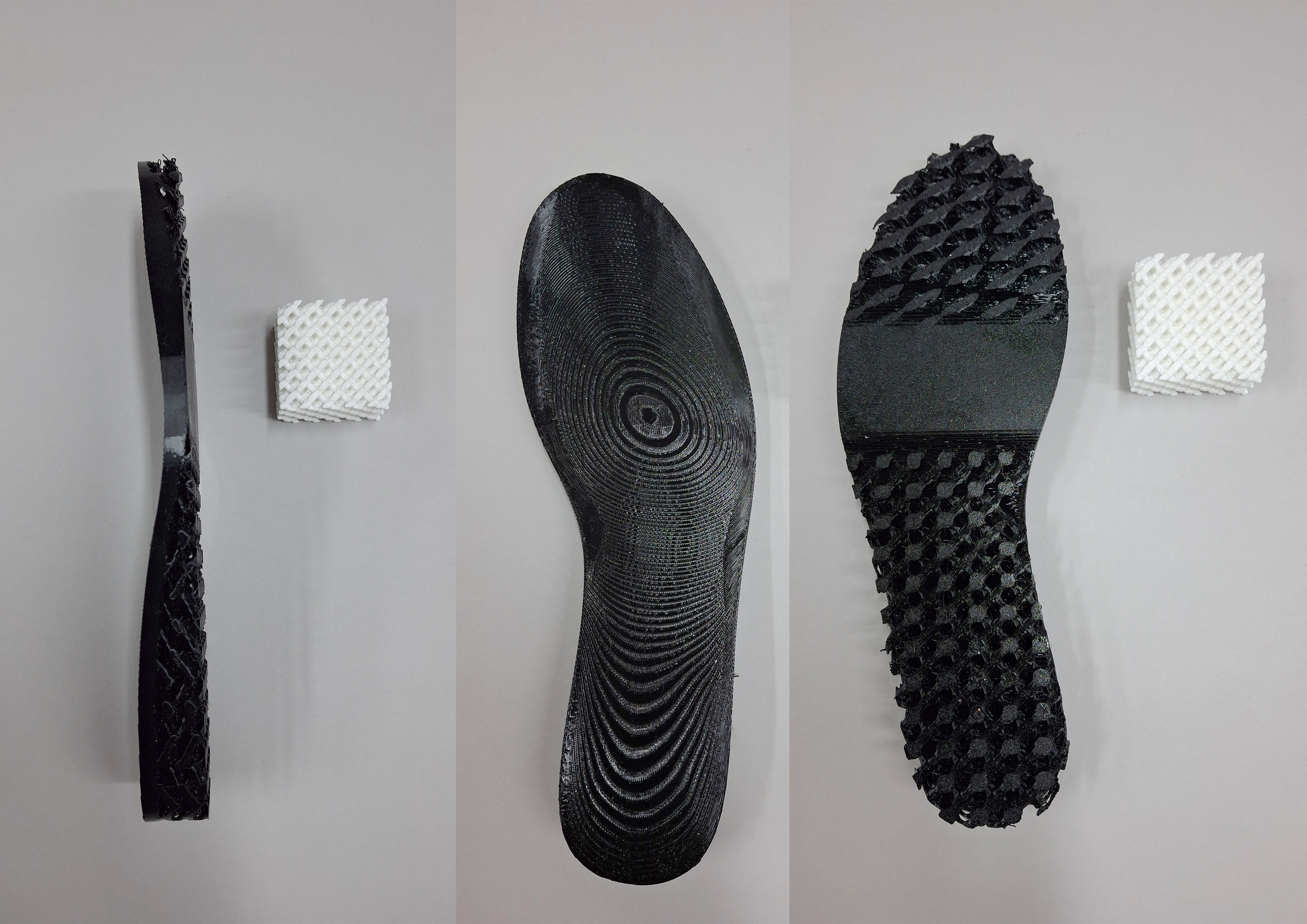
Because the perimeter frame in the previous design created problems, I redesigned the insole around a single lattice structure. Its density changes according to the plantar pressure map, creating stronger and softer support in different regions.
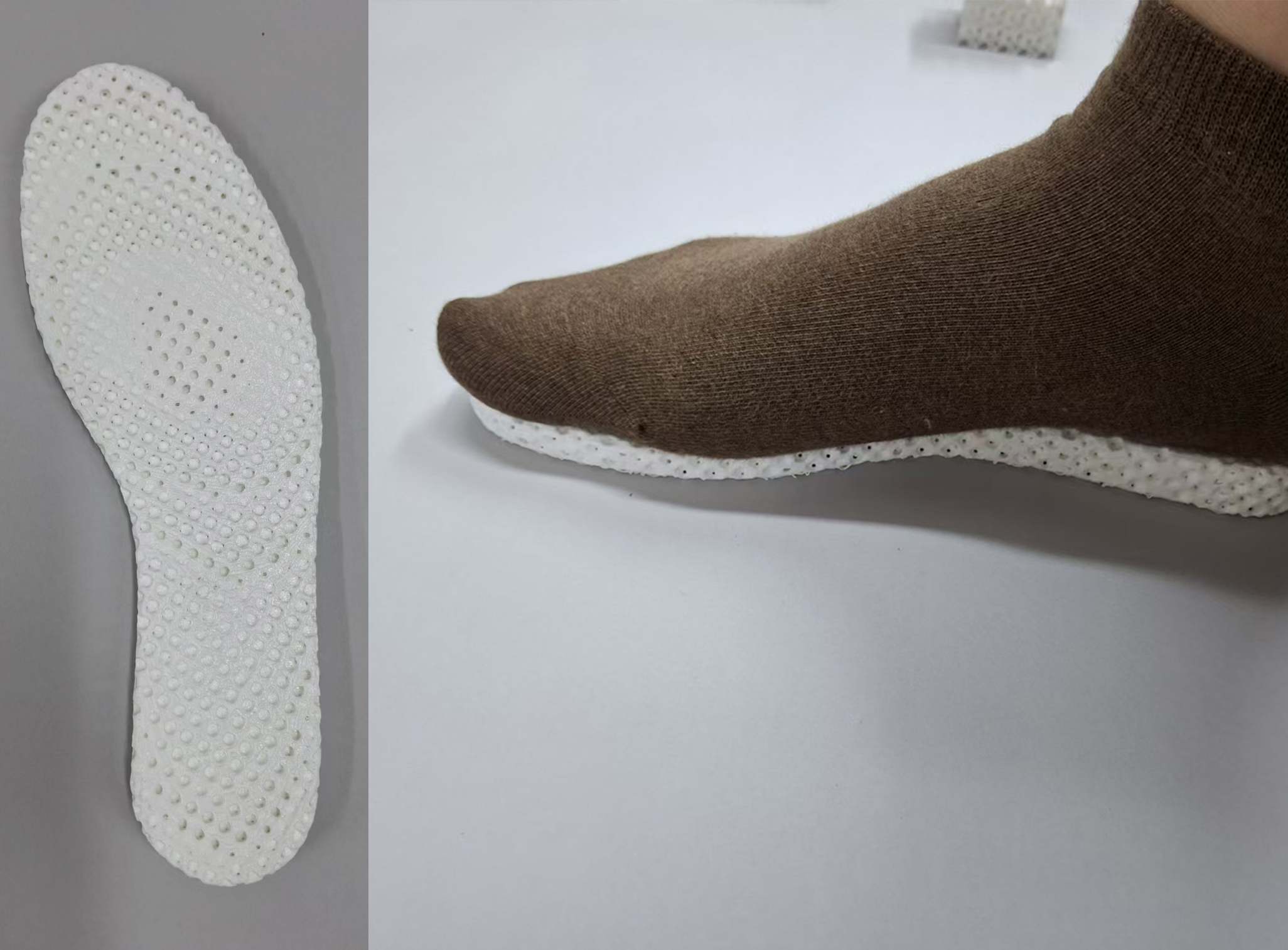
After all these tests, one version still felt the most comfortable.
Sometimes technical complexity is not the goal. Returning to the basics—comfort, enough elasticity, and a feeling that the foot can spring back—may matter more.
READING + CONTEXT
MakerBot Design Series: The Running Shoe — Core77, 2018 ↗
A related example of parametric lattice exploration and iterative prototyping.